
I. Overview of the Charging System
The charging system is the energy supply system for new energy vehicles, ensuring continuous power supply for vehicle operation.
Features of the charging system: It controls the start and stop of charging based on the real-time status of the power battery; and regulates the charging current and battery heating based on the battery’s charge level and temperature. The charging mode (i.e., fast charging or slow charging) can be selected according to the required charging time.
II. Charging System Structure and Principles
1. Fast Charging Mode
① Components: Mainly composed of ev charging equipment (charging station), high-voltage control box, power battery, vehicle control unit, high-voltage wiring harness, and low-voltage control wiring harness.

② System Structure Diagram of Fast Charging Mode
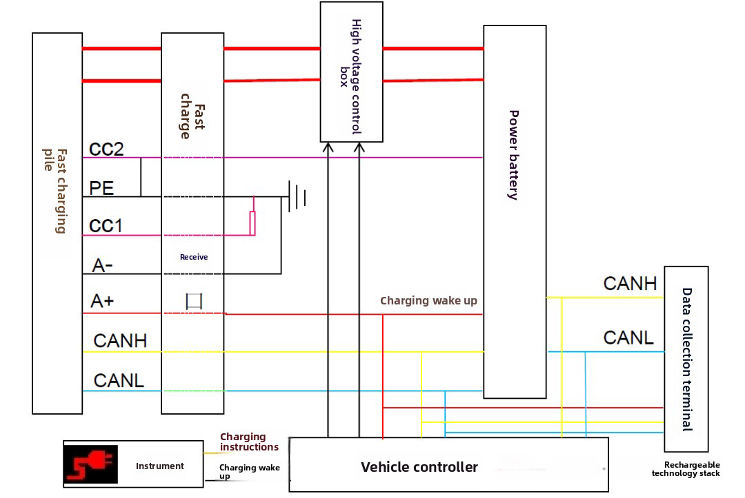
③ Charging Condition Requirements
- 1. Charging cable connection confirmation signal is normal;
- 2. BMS power supply is normal (12V);
- 3. Charging wake-up signal output is normal (12V);
- 4. Communication between charging station, VCU, and BMS is normal (main relay closed, current intensity demand sent);
- 5. Power battery cell temperature > 5℃ / < 45℃;
- 6. The difference between the highest and lowest single-cell voltage is < 0.3V (300mV);
- 7. The difference between the highest and lowest single-cell temperature is < 15℃;
- 8. Insulation performance > 20MΩ;
- 9. The actual highest single-cell voltage is not greater than the rated single-cell voltage by 0.4V;
- 10. High and low voltage circuit connections are normal (remote switch in closed state);
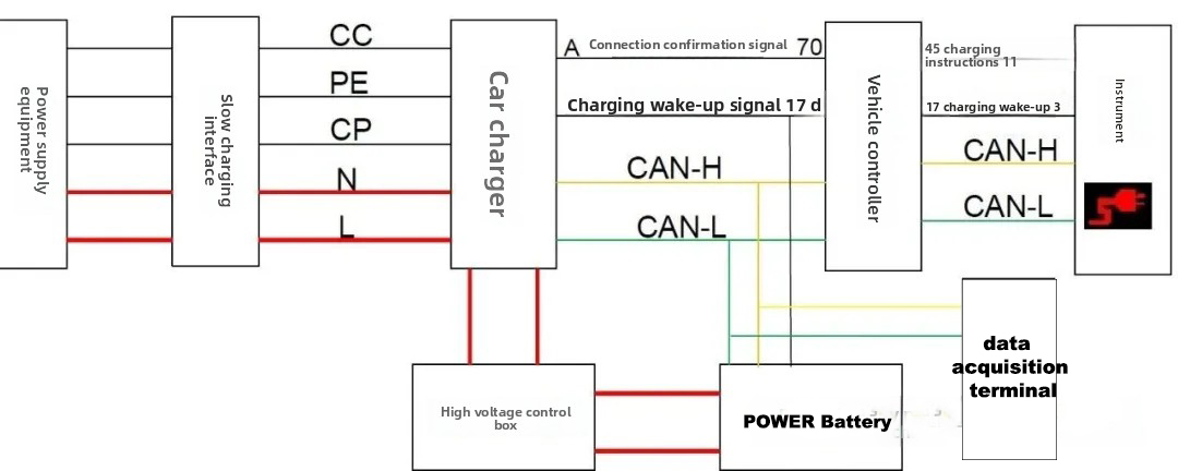
2. Slow Charging Mode
① Components: Mainly consists of a power supply device (AC charging station), on-board charger, high-voltage control box, power battery, vehicle controller, high-voltage wiring harness, and low-voltage control wiring harness.
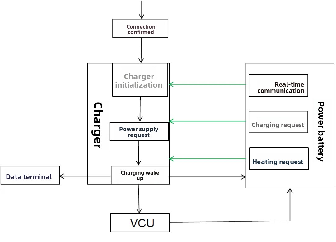
② Slow Charging Mode Structural Diagram
Principle:
- The charging gun connection is fed back to the VCU through the ev charger, which then wakes up the instrument panel to display the connection status (negative trigger);
- The charger simultaneously wakes up the VCU and BMS (positive trigger), and the VCU wakes up the instrument panel to start displaying the charging status (negative trigger);
- The positive and negative main relays are controlled by the BMS based on commands issued by the VCU.
③ Slow Charging Mode Working Principle
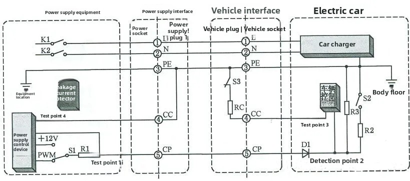
- Note: After the charging station confirms the connection signal via CC, it switches the S1 switch from the 12V terminal to the PWM terminal; when the voltage at detection point 1 drops to 6V, the charging station closes the K1/K2 switches to output current.
④ Charging Control Process
- a. AC power supply;
- b. Charging wake-up;
- c. BMS detects charging requirements;
- d. BMS sends working instructions to the on-board charger and closes the relay;
- e. The on-board charger starts working and begins charging;
- f. After the battery detects that charging is complete, it sends a stop command to the on-board charger;
- g. The on-board charger stops working;
- h. The battery disconnects the relay;
⑤ Charging Condition Requirements
- a. Charging cable connection confirmation signal is normal;
- b. Charger power supply is normal (including 220V and 12V) and the charger is working normally;
- c. Charging wake-up signal output is normal (12V);
- d. Communication between the charger, VCU, and BMS is normal (main relay closed, current intensity requirements sent);
- e. Power battery cell temperature > 0 ℃ / < 45 ℃;
- f. The difference between the highest and lowest single-cell battery voltage is < 0.3V (300mv);
- g. The difference between the highest and lowest single-cell battery temperature is < 15 ℃;
- h. Insulation performance > 20MΩ;
- i. The actual highest single-cell voltage is not greater than the rated single-cell voltage by 0.4V;
- j. High and low voltage circuit connections are normal (remote control switch in the closed state);
III. Charging Equipment Functions and Technical Parameters
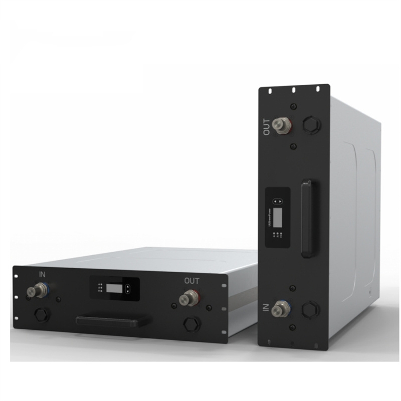
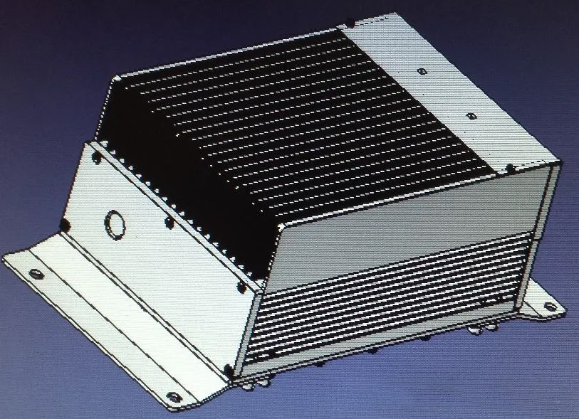
1. On-board Charger
Functions:
① The on-board charger converts the input AC power into DC power output;
② The on-board charger needs to communicate with the charging station, BMS, and VCU during operation;
③ The output power can be adjusted according to the power battery requirements.
2. DC/DC Converter
Function:
Converts the high-voltage electricity output from the power battery or charger into low-voltage electricity to charge the auxiliary battery and power the low-voltage system.
DC/DC Converter Working Process:
- a. The VCU receives the power-on signal or charging wake-up signal.
- b. The power battery completes the high-voltage system pre-charging process.
- c. The VCU sends an enable signal to the DC/DC converter.
- d. The DC/DC converter starts working.
Post time: Jan-23-2026


