Analysis of the Complete Operational Workflow for DC Charging Pile Communication Protocols
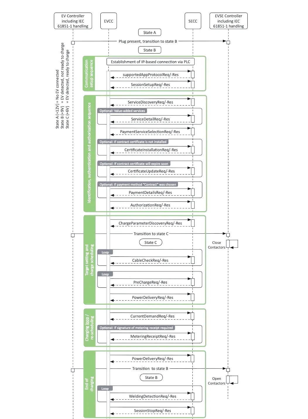
This diagram illustrates the complete communication sequence between an electric vehicle (EV) and an EV supply equipment (EVSE) unit during DC fast charging, based on the ISO 15118-2 / DIN 70121 protocols. There are four participating roles in the diagram:
EV Controller (Includes IEC 61851-1 CP signal processing)
EVCC (Electric Vehicle Communication Controller)
SECC (Supply Equipment Communication Controller)
EVSE Controller (Includes IEC 61851-1 CP signal processing)
The vertical text on the left explains the meanings of the CP (Control Pilot) states: State A (+12V) = vehicle not connected; State B (+9V) = vehicle detected but not yet ready to charge; State C (+6V) = vehicle detected and ready to charge. The entire process is divided into six color-coded stages, which are explained in detail below.
I. Initial Connection (State A → State B)
1
Plug present, transition to State B After the charging connector is plugged into the vehicle, the CP resistance on the EV side changes. The EVSE detects the duty cycle signal, and the CP state switches from A to B, indicating “vehicle detected but not yet ready to charge.” At this point, both sides enter State B.
II. Communication setup sequence (Communication establishment phase; the first green block)
1
Establishment of an IP-based connection via PLC Physical layer pairing (the SLAC process) between the vehicle and the charging station is completed using Power Line Communication (PLC—specifically, the HomePlug Green PHY mentioned earlier in the report), followed by the establishment of an IPv6-based network connection (SDP discovery and TCP connection setup). This step corresponds to the physical/data link layer aspects analyzed previously.
2
supportedAppProtocolReq / -Res The EVCC sends the SECC a list of the application-layer protocol versions it supports (e.g., DIN 70121, ISO 15118-2, etc.). The SECC selects a protocol version supported by both parties and responds, thereby determining the protocol “dialect” to be used for subsequent communication.
3
SessionSetupReq / -Res The EVCC initiates a session setup request (containing the EVCC ID), and the SECC assigns or confirms a SessionID. A V2G communication session is formally established between the two parties, and all subsequent messages carry this SessionID.
III. Identification, authentication, and authorization sequence (Green section, second block)
1
ServiceDiscoveryReq / -Res The EVCC queries the SECC regarding supported services (e.g., DC charging, value-added services) and payment methods (e.g., EIM—External Identification Means—or Contract-based certificate authentication).
2
(Optional) ServiceDetailReq / -Res If value-added services are available, the EVCC can further query the detailed parameters for a specific service.
3
PaymentServiceSelectionReq / -Res The EVCC selects the service and payment method to be used and notifies the SECC.
4
(Optional) CertificateInstallationReq / -Res If the vehicle does not yet have a Contract Certificate installed, it can use this message to request installation from the backend (relayed via the SECC) for Plug & Charge scenarios.
5
(Optional) CertificateUpdateReq / -Res If the vehicle already possesses a Contract Certificate but it is nearing expiration, a certificate update is requested.
6
(Optional) PaymentDetailsReq / -Res If the selected payment method is “Contract” (i.e., automated payment via contract certificate authentication, known as Plug & Charge), the EVCC sends payment-related information, such as the certificate chain, for validation.
7
AuthorizationReq / -Res The EVCC requests authorization to start charging, and the SECC confirms that the vehicle/user has been authorized (whether via certificate, external card swipe, or App-based authorization); this step may require polling until the authorization status changes to “Finished.”
IV. Target setting and charge scheduling (Target Setting and Charging Schedule Phase; third green section)
1
ChargeParameterDiscoveryReq / -Res The EVCC reports the vehicle’s charging parameter requirements (such as maximum voltage/current/power, current battery SOC, energy demand, etc.), and the SECC responds with the charging capability parameters available from the EVSE side (maximum output voltage/current/power, etc.); based on this information, the two parties negotiate a feasible charging curve.
2
Transition to State C After parameter negotiation is complete, the CP resistance on the EV side changes again (this action is usually accompanied by preparations for contactor closure), and the CP state switches from B to C, indicating that the “vehicle is ready and charging can begin.”
3
Close Contactors (EVSE-side action): Upon detecting State C, the EVSE closes the DC contactors to prepare for subsequent voltage application (actual current flow does not occur yet; insulation/cable checks must be performed first).
4
Loop: CableCheckReq / -Res The EVCC and SECC exchange messages cyclically to perform an insulation test on the charging cable, confirming proper insulation to ground for both the cable and the vehicle-side circuit; the EVSEProcessing status indicates whether the check is complete (the loop is exited only when the status is “Finished”).
5
Loop: PreChargeReq / -Res During the pre-charge phase, the EVSE slowly adjusts its output voltage to match the vehicle’s battery voltage, preventing an excessive current surge upon closing the main contactors. The EVCC continuously reports the measured voltage on the vehicle side, and the loop is exited only when the voltages match (i.e., the EV determines the voltage has been sufficiently adjusted to the RESS voltage).
6
PowerDeliveryReq / -Res The EVCC requests the formal start of power delivery (ReadyToChargeState=true); upon confirmation by the SECC, the EVSE output contactors/power stage are enabled, and actual charging begins.
V. Charging loop / re-scheduling (Charging loop/re-scheduling phase; fourth block, in green)
1
CurrentDemandReq / -Res (Loop) This is the core, continuously looping message pair during the charging process. The EVCC periodically transmits the vehicle’s current voltage and current requirements (e.g., EVTargetCurrent, EVTargetVoltage, EVMaximumCurrentLimit), while the SECC responds with the actual output voltage/current and the EVSE-side status (such as whether current limits have been reached or faults have occurred). This loop persists throughout the entire charging process and represents the key interaction for adjusting charging power on demand.
2
(Optional) MeteringReceiptReq / -Res If signed confirmation of metering data is required (e.g., involving billing records), the EVCC periodically sends a receipt request containing the signed metering values, and the SECC acknowledges it. This step is optional and depends on whether the business logic requires metering signatures.
VI. End of charging (Charging termination phase; fifth green block)
1
PowerDeliveryReq / -Res When the vehicle (or user) decides to stop charging, the EVCC sends a Power Delivery Request with the parameter `ReadyToChargeState=false`, notifying the SECC to halt power output.
2
Transition to state B After power delivery ceases, the CP state switches from C back to B, indicating that although the vehicle remains connected, charging has stopped.
3
Open Contactors (EVSE-side action): The EVSE opens the DC contactors and disconnects the high-voltage circuit to ensure safety.
4
Loop: WeldingDetectionReq / -Res After the contactors open, “Welding Detection” is performed; the EVCC/SECC cyclically checks whether the contactors failed to truly disconnect due to welding and confirms that the output voltage has indeed dropped to a safe level.
5
SessionStopReq / -Res The EVCC sends a Session Stop Request (specifying either “Terminate” or “Pause”). Upon SECC confirmation, the entire V2G communication session is formally closed, and the charging process concludes.
Summary of Overall Logic
In essence, this sequence diagram illustrates the complete closed-loop process of DC charging: from physical connection → network and protocol negotiation → identity authentication and authorization → parameter negotiation and safety checks (insulation/pre-charge) → actual power delivery and regulation → safe termination. Specifically:
State Machine Level
The CP state sequence (A→B→C→B) corresponds strictly to the overall communication process, ensuring that communication states remain synchronized with the actions of physical relays or contactors—a core mechanism for guaranteeing charging safety.
Message Level
Almost all stages follow a “Request (Req)/Response (Res)” pairing pattern. Certain stages are marked with loop indicators (e.g., Cable Check, Pre-charge, Current Demand, Welding Detection), signifying that these interactions repeat until specific exit conditions are met (such as voltage matching, insulation compliance, or confirmation of contactor disconnection).
Optional Branches
(Indicated by gray “Optional: …” labels in the diagram) demonstrate the protocol’s flexibility across different scenarios—such as certificate installation/updates, metering signatures, or value-added services—none of which are mandatory steps for every charging session.