
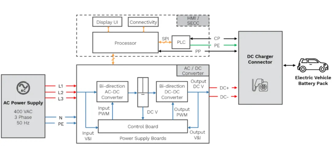
Based on this architecture diagram, the entire system can be divided into five major modules:
1. AC Power Supply
- ● A three-phase 400 VAC, 50 Hz power supply is connected via a total of five lines: three phase lines (L1, L2, L3), a neutral line (N), and a protective earth line (PE).
- ● The power from L1, L2, and L3 is routed to the main power circuit of the AC/DC converter, while the N and PE lines are connected to the control board and downstream equipment for monitoring and protective grounding purposes, respectively.
2. AC/DC Converter (Power Supply Boards / Main Power Module)
This is the core power conversion section of the charging pile, comprising two stages:
- Bi-directional AC-DC Converter Rectifies three-phase AC into an intermediate DC bus voltage (represented as “DC V” in the diagram, corresponding to the central capacitor/bus symbol) and supports bi-directional energy flow (enabling V2G scenarios).
- Bi-directional DC-DC Converter Converts the bus voltage into an output voltage (Output DC V) suitable for charging the electric vehicle battery; it also supports bi-directional flow.
- Control Board Located at the bottom, this board acquires input-side voltage and current (Input V&I) and output-side voltage and current (Output V&I). It generates Input PWM and Output PWM signals to drive the power switches of the two conversion stages, thereby achieving closed-loop control.
- The module ultimately outputs DC+ and DC- lines from the DC bus to the DC charging gun connector.
3. Host Controller/HMI Module (Processor + HMI/SECC)
The area within the dashed box represents the control and interaction layer:
- Processor (Main Processor) The “brain” of the system; it communicates with the PLC via an SPI bus and maintains a bidirectional connection with the AC/DC converter module below (to acquire status data and issue control commands). Simultaneously, it drives the Display UI (screen) and Connectivity modules (e.g., 4G, Ethernet) located above.
- PLC (Power Line Communication Module; part of the HMI/SECC—Human-Machine Interface/Supply Equipment Communication Controller) Responsible for exchanging CP (Control Pilot) and PP (Proximity Pilot) signals with the electric vehicle via the charging gun. It complies with DC fast-charging communication protocols such as CCS or GB (e.g., ISO 15118 or GB/T 27930) and transmits the PE (Protective Earth) signal.
4. DC Charger Connector
Consolidates the DC+ and DC- main power lines from the power modules and the CP, PP, and PE signal lines from the PLC; it establishes a physical connection and enables bidirectional communication with the EV battery pack via the charging gun.
5. EV Battery Pack
The final power-receiving unit; it interacts bidirectionally with the charging gun (receiving electrical energy while simultaneously providing feedback on battery status, SOC, and other data via CP/PP lines for charging control).
Overall Signal/Energy Flow Summary
- Energy Flow (thick red/blue lines)
AC Power Supply → AC/DC Converter (two-stage power conversion) → DC+/DC- → Charging Gun → Battery Pack. - Control Flow (orange arrows)
Processor ⇄ AC/DC Converter (exchange of power stage status and commands); Processor ⇄ PLC (SPI communication). - Communication Flow (black arrows)
PLC ⇄ Vehicle (CP/PP signals for handshake, authentication, voltage/current requests, etc.).
This is a typical architecture for a DC fast-charging station. A two-stage power conversion scheme (AC-DC + DC-DC) facilitates the independent optimization of power factor correction and the output voltage regulation range; the control board handles low-level real-time control, the processor manages high-level operations and human-machine interaction, and a PLC is dedicated to handling vehicle-to-charger communication protocols.
Post time: Sep-09-2026


