
The architectural design of a V2G DC charging station compliant with European standards (CCS2 interface) involves the coordinated design of three layers: power hardware, control electronics, and communication protocols. A comprehensive technical framework is outlined below to serve as a basis for further refinement.
I. Overall System Architecture
The system comprises four major functional modules:
- Power Conversion Module: Handles bidirectional AC/DC conversion; serves as the core for bidirectional V2G energy flow.
- Control and Protection Module: Includes the main controller, safety interlocks, and insulation monitoring.
- Communication Module: Vehicle-to-charger communication (EVCC-SECC) and charger-to-cloud communication (backend management).
- HMI/Metering Module: Display, billing and metering, and RFID/App-based authentication.
II. Hardware Architecture (Power Stage)
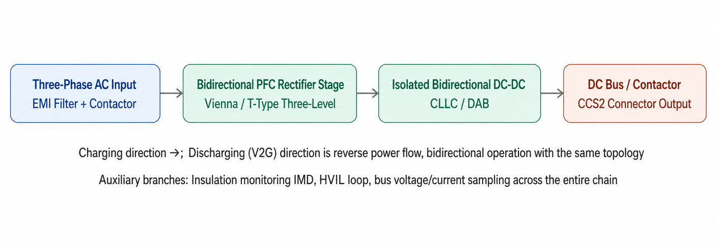
The core enabler for V2G support in CCS2 DC charging stations is a bidirectional, isolated power conversion link; compared to standard unidirectional chargers, this architecture incorporates an inversion (discharge) path and requires stricter power quality control.
Key Design Points
1. Front-end Three-phase AC/DC (PFC Rectifier Stage)
- Topology: Three-level Vienna rectifier (unidirectional applications are common, but V2G scenarios typically utilize bidirectional three-level topologies, such as a three-phase voltage-source AC/DC stage with SiC MOSFETs for bidirectional power flow, or a T-type three-level bridge).
- Components: SiC MOSFETs (650V/1200V) are widely used for power ratings above 30 kW; switching frequencies range from 20 to 50 kHz to balance efficiency and the size of magnetic components.
- Functions: AC/DC rectification (G2V) + DC/AC inversion (V2G) + decoupled active/reactive power control (for grid support and frequency/voltage regulation scenarios).
- Power Quality: Must comply with standards such as IEC 61000-3-12 (harmonics) and EN 50549 (grid connection protection); THD is typically required to be <5% during V2G discharge.
2. Isolation Stage: Bidirectional DC-DC Converter
- Preferred Topologies: CLLC resonant converter (bidirectional symmetry, high soft-switching efficiency, suitable for fixed or narrow-range voltage gain) or Dual Active Bridge (DAB) (superior dynamic response over a wide voltage range, accommodating battery voltage platforms from 150V to 1000V across different vehicle models).
- The isolation transformer must be designed to the highest insulation class (vehicle-to-charger isolation to prevent coupling between the vehicle chassis potential and the grid potential).
- This stage also serves as the point of electrical isolation mandated by the CCS2 standard (both GB/T 27930 and IEC 61851-23 require electrical isolation between the vehicle and the charging station).
3. DC Bus and Output Stage
- Bus capacitor + DC bus voltage/current sensing (for V2G power loop control)
- DC contactors (one each for positive and negative poles; some designs include a pre-charge resistor and pre-charge contactor for soft-starting the DC bus after the CCS2 connector is plugged in)
- HVIL (High Voltage Interlock Loop): Extends through the entire path from the connector to the DC bus and converter; output is cut off if the circuit is broken at any point
- Insulation Monitoring Device (IMD): Real-time monitoring of insulation resistance to ground for both positive and negative DC buses; triggers protection upon detecting a fault
III. Communication Architecture
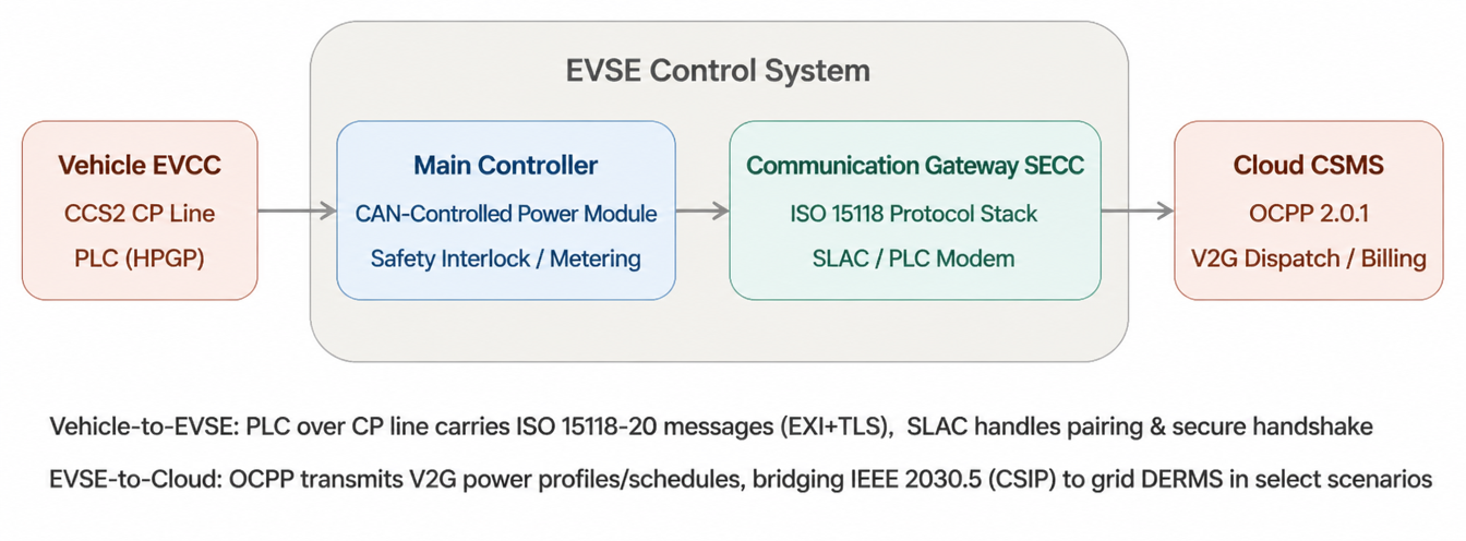
Communication for CCS2 DC V2G comprises two layers: vehicle-to-charger communication (EVCC↔SECC) and charger-to-cloud communication (SECC↔CSMS); the former is critical to enabling bidirectional V2G dispatch.
In-depth Explanation of Communication Protocol Stacks
1. Vehicle-Charger Layer (EVCC ↔ SECC)
| Layer | Protocol / Standard | Function / Description |
|---|---|---|
| Physical Layer | CP Line (Control Pilot) | Carrier channel; backward-compatible with IEC 61851 basic state detection. |
| Data Link Layer | HomePlug GreenPHY (PLC) | Superimposes high-speed Power Line Communication (PLC) onto the CP line. |
| Pairing / Discovery | SLAC | Physical vehicle-to-EVSE pairing; prevents crosstalk. |
| Transport Layer | V2GTP | UDP / TCP encapsulation. |
| Security | TLS 1.2 / 1.3 + V2G PKI | Mutual authentication. |
| Application Layer | ISO 15118-20 | Bidirectional power transfer parameter negotiation. |
| Encoding | EXI | Message compression and binary encoding. |
A key addition in ISO 15118-20 compared to ISO 15118-2 is the BPT (Bidirectional Power Transfer) service. To ensure compatibility with the domestic GB/T standard system, it is also necessary to consider the compatibility layer between GB/T 27930 (current version) and GB/T 27930-202x.
2. Internal Bus (Main Controller ↔ Power Module)
- Typically utilizes CAN 2.0B or CAN FD; the main controller issues voltage/current commands to the power modules, while the modules report status and fault codes.
- If a modular power architecture is used, master-slave arbitration and load-sharing protocols are also required.
3. Charger-to-Cloud Layer (SECC ↔ CSMS)
- OCPP 2.0.1: Currently the mainstream choice; its Bidirectional Power Transfer module specifically supports the transmission of power profiles and the reporting of energy metering data for V2G scenarios.
- For projects involving grid frequency regulation or demand response, IEEE 2030.5 (CSIP) or OpenADR may be used.
Safety and Compliance Highlights (V2G-Specific)
- Anti-islanding Protection: In discharge mode, the system must comply with IEC 62116/UL 1741.
- Bidirectional Metering: Metering chips must support bidirectional energy measurement and separate billing.
- Power Factor and Harmonics: Grid-connection harmonic limits must be met during discharge.
- Certification: Compliance with CE, EN 61851-23, and EN 62477-1 must be considered.
Post time: Sep-28-2026


