Design of Single-Phase/Three-Phase AC EV Charging Stations
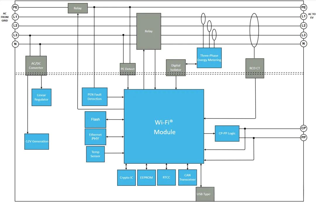
The figure below illustrates the electrical and control architecture of a typical single-phase/three-phaseAC EV charging station. The dashed line represents the isolation boundary between high-voltage/high-power circuits and low-voltage/control circuits (with the high-voltage/primary side above and the low-voltage/control side below). It can be analyzed in terms of four major functional modules:
1. Power Input and Output (Main Circuit)
Input SideGrid-side connections include PE (Protective Earth), L1/L2/L3 (three-phase live lines), and N (neutral line).
Output SideThe same PE/L1/L2/L3/N lines are output to the electric vehicle. Additionally, there are two signal lines—CP (Control Pilot) and PP (Proximity Pilot/Plug Present)—which carry the core signals used for the communication handshake between the charging station and the vehicle, as defined by the IEC 61851 and SAE J1772 standards.
Main Relays (Large Relays)Connected in series with the L1, L2, and L3 phases, these serve as the primary switches that actually connect or disconnect the vehicle’s charging current; they are driven directly by the Wi-Fi module (main controller).
PE Relay (Small Relay at the Top)Connected to the PE circuit and working in conjunction with the PE detection module below, this relay checks for a reliable ground connection. It is a critical component of leakage and grounding protection; many standards (such as GB/T 18487) require verifying PE continuity before closing the main relays.
2. Safety Protection Chain
This is the most critical component of the entire design, demonstrating the multiple safeguards the ev charging station provides for personal safety:
PE Detect + PEN Fault DetectionMonitors the grounding status and detects any breakage in the PEN line (where the Neutral and PE lines are combined, as in some single-phase systems); any detected anomaly triggers immediate feedback to the main controller to cut off the relay.
RCD CTA current transformer encircling all phase lines and the neutral line to monitor leakage current (residual current); it detects minute differential currents caused by electric shock or insulation faults and serves as a core safety component.
Digital IsolatorTransmits detection signals from the high-voltage side (such as analog signals from the RCD CT) to the main controller on the low-voltage side; this ensures electrical isolation between the control system and the high-voltage circuit, preventing high voltage from surging into the low-voltage side.
3. Metering and Control Core
Three-Phase Energy MeteringUses three independent current transformers (CTs) to sample currents from phases L1, L2, and L3 for three-phase energy metering (billing/statistics)—a signature module of commercial charging stations (as opposed to residential units).
Wi-Fi Module (Main Control Chip)The brain of the entire system; integrates Wi-Fi connectivity and directly manages:
Main relay switching (on/off)
PEN fault detection results
CP-PP logic (reads vehicle connection status and negotiates charging current)
Three-phase metering data
Various peripherals
4. Peripherals and Auxiliary Power Supply
Control-side PeripheralsFlash (program/data storage), Ethernet PHY (wired network backup), Temp Sensor (temperature monitoring/overheat protection), Crypto IC (encryption chip for billing data/OCPP communication security authentication), EEPROM (configuration parameter storage), RTCC (real-time clock for recording charging timestamps), CAN Transceiver (likely for interfacing with the vehicle CAN bus or communicating with other internal boards), USB Type-A (interface for debugging, firmware upgrades, and maintenance).
Auxiliary Power Supply PathAn AC/DC converter draws power from the L3-N line; a linear regulator outputs a positive voltage to power the control board, while a separate circuit generates -12V—presumably to produce the ±12V PWM levels for the CP signal (the CP signal standard specifies a ±12V square wave, with the vehicle and charging station negotiating charging current via the duty cycle).
Overall Design Logic
This architecture employs a classic design that isolates high-voltage control from low-voltage communication: the main controller (Wi-Fi module) safely acquires fault detection data (PE, PEN, and leakage current) and metering information from the high-voltage side via isolators to decide whether to engage the relays. Simultaneously, it performs a handshake with the vehicle via CP-PP logic to negotiate charging parameters and connects to the cloud—using Wi-Fi or Ethernet—for remote monitoring, billing, and OTA updates. This design generally aligns with the standard architecture of mainstream commercial-grade AC charging stations (featuring energy metering and cloud management capabilities).