
Plug and Charge (PnC) is a core function defined by ISO 15118: once the charging cable is plugged in, authentication and billing linkage occur automatically through the exchange of digital certificates between the vehicle and the charging station—eliminating the need for card swipes, QR code scanning, or app interactions. The communication process is broken down chronologically below.
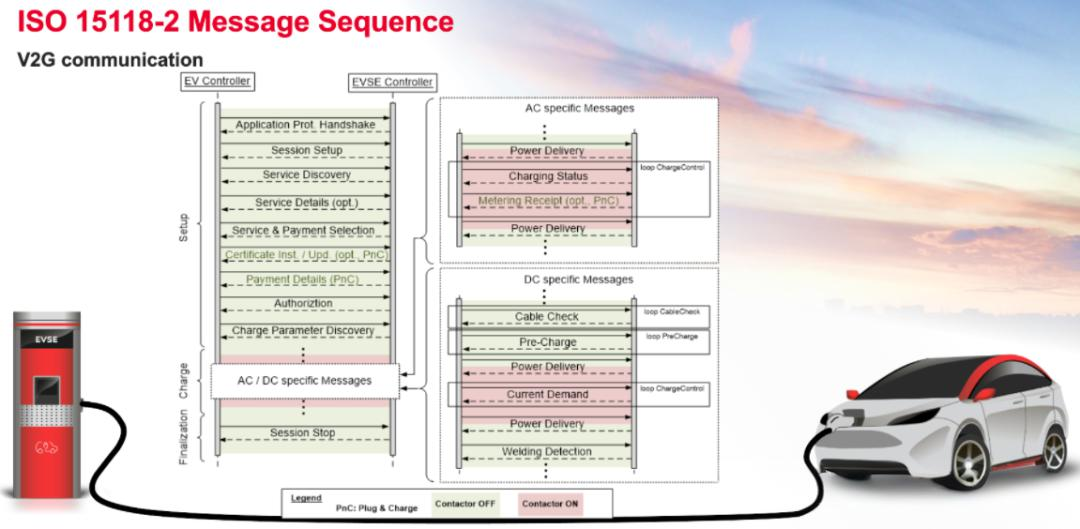
PnC communication relies on the ISO 15118 protocol stack; essentially, it is a process of upgrading layer-by-layer from a “physical layer handshake” to “application-layer secure communication” between the vehicle and the station. The process comprises five stages:
Stage 1: Basic Analog Layer Handshake (IEC 61851; no digital communication involved)
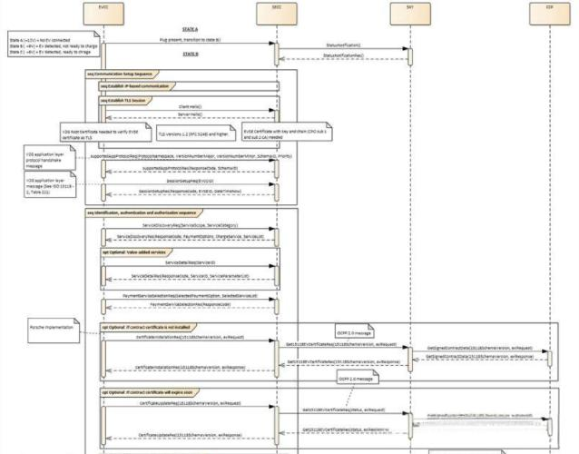
After the cable is plugged in, the voltage level on the Control Pilot (CP) line drops from 12V to 9V (State B). Upon detecting this, the EV charging station’s control board begins outputting a PWM square-wave signal (indicating the maximum available charging current). This step merely informs the vehicle that charging is available and specifies the maximum current limit; it involves purely analog signals and does not yet constitute the actual PnC process.
Stage 2: PLC Link Establishment (SLAC Matching)
Once the PWM signal stabilizes, if the vehicle determines it will proceed with the ISO 15118 process (indicated by the duty cycle switching to a fixed 5%), the PLC modules in both the vehicle and the station activate. The station continuously broadcasts SLAC beacon frames. By comparing signal attenuation across multiple beacons, the vehicle identifies exactly which CP line it is connected to—thereby pairing with the correct charging station—and both parties generate a shared network key to establish a point-to-point PLC communication link. This step resolves the question: “Which specific station am I connected to within a group of stations?”
Phase 3: TCP/TLS Session and Authentication (The Core of PnC)
This is the critical stage where Plug and Charge truly distinguishes itself from traditional “tap-to-charge” methods:
Phase 4: Charging Parameter Negotiation and Power Delivery Initiation
Following successful authentication, the parties exchange ChargeParameterDiscoveryReq/Res messages; the vehicle reports its maximum acceptable current and voltage, while the DC charging station reports its maximum available current and voltage. The actual charging parameters are determined by identifying the intersection of these values. Once negotiation is complete, the vehicle sends a PowerDeliveryReq to request power; the station then closes the K1/K2 relays and begins outputting AC power.
Phase 5: Charging Process and Termination
Throughout the charging process, the parties continuously exchange real-time status information (e.g., via ChargingStatusReq/Res) over the PLC channel, with the station dynamically adjusting the available current based on grid load or vehicle status. To end the session, the vehicle initiates a SessionStopReq; the station opens the relays, and both parties terminate the PLC network connection. Simultaneously, charging data (such as energy consumption) is processed via the operations platform for billing and settlement—all without requiring the vehicle owner to insert a card or scan a QR code.
Post time: Aug-19-2026


