
Recently, clients working with our company have frequently raised questions regarding three-phase power in the context of installing and using AC and DC charging stations. Consequently, today’s post is dedicated to addressing inquiries about the power distribution units used in these charging stations.
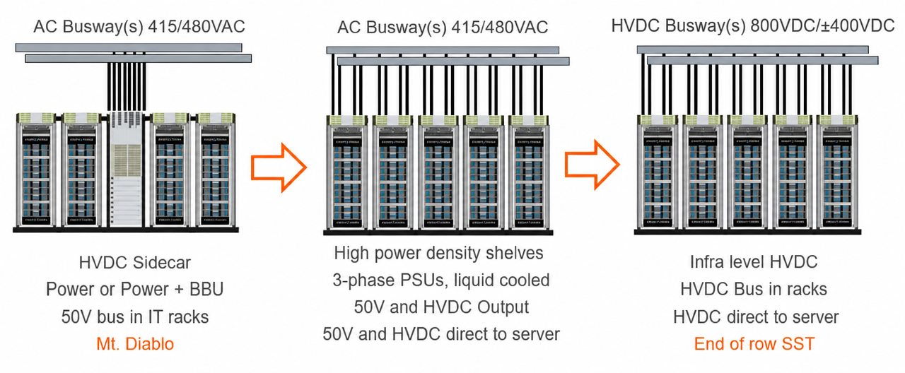
The protection and control module for three-phase AC input and ±400VDC output is expected to occupy a maximum space of 15 OU; further details are provided below.
1 AC PDU Configuration
The AC PDU draws power from an overhead busway and distributes it to the inputs of three separate three-phase power shelves. The AC PDU shall be designed to meet the following requirements:
- ✔ Support the connection of up to 16 x 200A AC cables or 24 x 100A AC cables.
- ✔ Include protective fuses.
- ✔ Input connections may be implemented using two-hole crimp lugs or connectors.
- ✔ Include an optional AC distribution panel/cabinet.
The three-phase output from the AC PDU is split into cables with lower current ratings (for example, a 200A feed may be split into four 50A cables), which are then routed to the individual power shelves to supply power to the three-phase PSUs.
2 ±400VDC Power Distribution
The ±400VDC output from the power shelf is collected and distributed via a vertical busbar that runs the entire height of the rack.
The ±400V supply—generated by either a power shelf or an energy storage unit—is transmitted through the rack busbar, which is also connected to the output protection and control module.
3 ±400VDC PDU Output Protection and Control Module
The DC charging station PDU module shall be designed to support an output of up to 400kW and incorporate manageability, output switching (on/off), protection, and telemetry functions. The output cables shall be free of voltage at their contacts.
- ● Option 1: 50kW per cable; the number of cables is determined by the required output power range.
- ● Option 2: 100kW per cable; the number of cables is determined by the required output power range.
- ● The output protection and control module shall connect to a ±400VDC or differential 800VDC busbar and feature multiple output connectors, which deliver power to IT racks via cables.
- ● Each output module supports multiple output cables, with two available configurations:
- ● The front panel of the output protection and control module shall be equipped with physical switches to turn the corresponding output connectors on or off.
- ● The output protection and control module shall include LED indicators, fuses, and relays to provide overcurrent protection for each output circuit.
- ● Output Voltage Disconnection: For each circuit, the voltage at the connector must be disconnected before the cable is unplugged from either the power source side or the load side; the connection must also remain disconnected when no output cable is installed.
- ● Optional: Active management via a microcontroller to ensure safe access.
- ● Optional: Interface with a Rack Management Unit.
4 PE Grounding
4.1. Midpoint Grounding for ±400Vdc
There are two methods for connecting the midpoint of a ±400Vdc system to PE (Protective Earth):
- High-impedance midpoint grounding to PE.
- Solid (direct) midpoint grounding to PE.
The midpoint grounding components must be shielded or covered to ensure protection against accidental contact. For ±400Vdc power distribution, the wiring within the rack and the cabling routed to IT racks can be configured as either 3-wire + PE (+400Vdc, midpoint/common, −400Vdc, and PE) or 2-wire + PE (where the midpoint is not extended to the IT racks).
4.1.1. High-Resistance Grounding
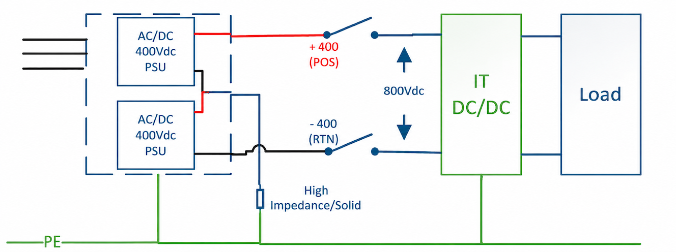
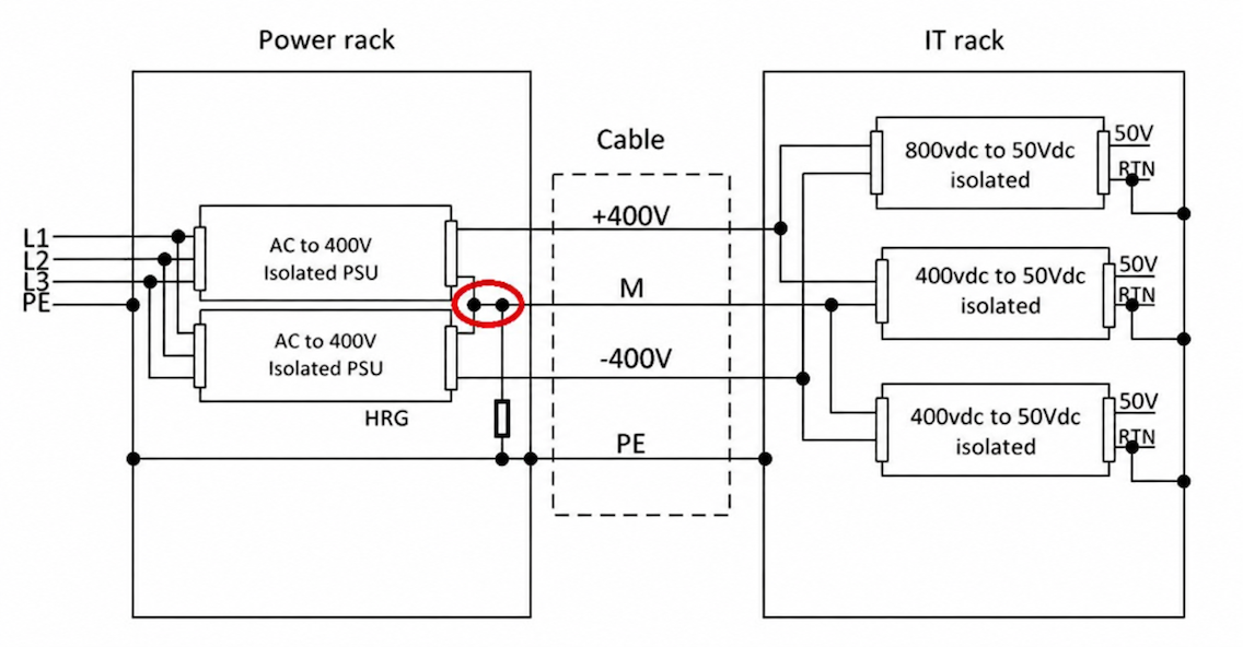
In this configuration, the midpoint can be connected to PE via a high-resistance grounding scheme, as shown in the figure below.
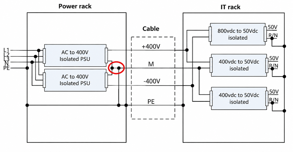
4.1.2. Direct Grounding
In this configuration, the midpoint can be connected to the PE (protective earth) via a solid connection, as shown in the figure below.
4.2. 800Vdc Grounding
For 800Vdc power distribution, the cabling within the rack and to the IT racks can be configured as a 2-wire + PE system (800Vdc, 0Vdc, and PE).
The 800Vdc output can remain floating, with a high-resistance ground applied to the return (RTN) terminal; alternatively, it can be implemented as a single-ended 800Vdc output, with the return terminal directly connected to PE—the specific approach depends on the chosen architecture.
4.2.1. High-Resistance Grounding
The figure below illustrates one possible configuration: for a floating 800Vdc output, the RTN (return) terminal is connected to PE via a high-resistance grounding scheme (with no midpoint connection).
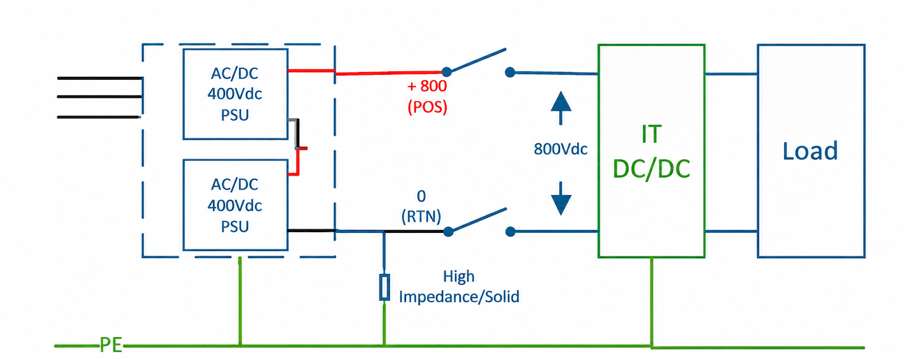
[The diagram shows two AC/DC 400Vdc PSUs connected in series, with outputs of +400Vdc (POS) and -400Vdc (RTN), totaling 800Vdc. They are connected to an IT DC/DC load and then to the PE.]
4.2.2. Direct Grounding
The figure below illustrates one possible configuration: for a single-ended 800Vdc output, the RTN (with no midpoint tap) is connected to PE via a solid connection.
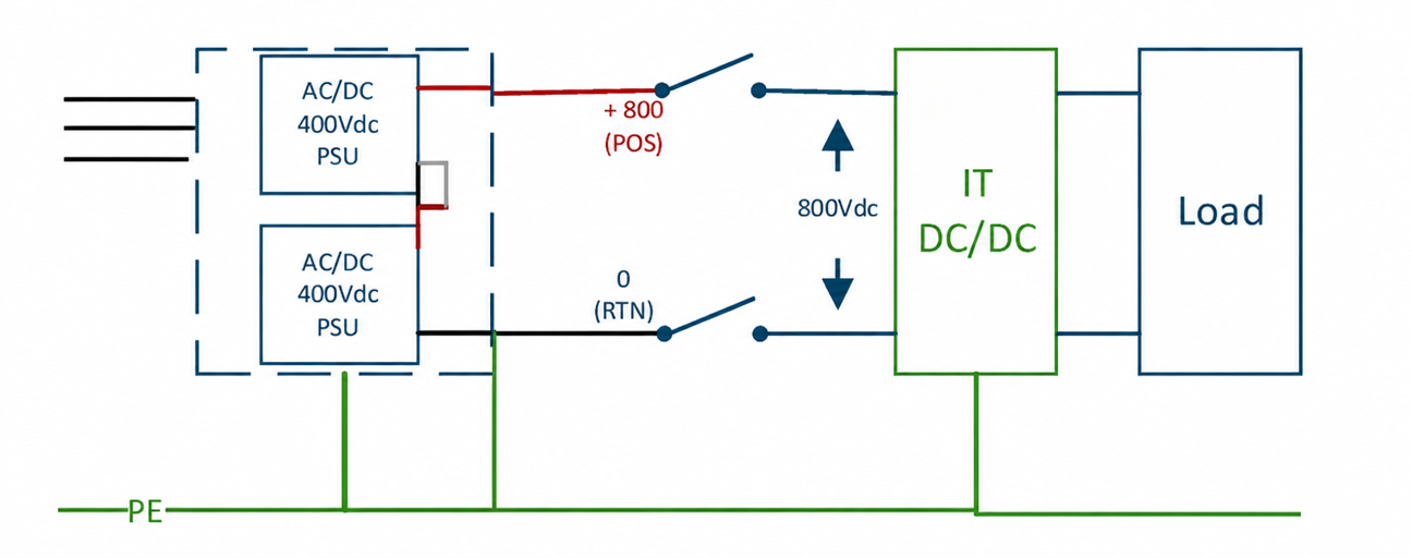
[The output shown in the diagram consists of +800 (POS) and 0 (RTN), with the RTN terminal actually connected to PE.]
4.2.3. Ground Fault Detector
A ground fault detector (GFD) shall be implemented, regardless of whether the neutral point is directly grounded or grounded through a high-resistance connection.
- In cases where the neutral point is grounded via a high-resistance connection, the GFD shall include a voltage-balance detection circuit.
- Optional: Active management via a microcontroller to ensure safe access.
- Optional: A modular interface to the rack management unit.
- Residual current detection shall be implemented for every output cable/connection leading to an IT rack.
Post time: Nov-17-2026


